Saturday, 25 May 2013


PROPERTIES OF FLUIDS

                              1. Density
                    
                              2. Specific weight (weight density)

                              3. Specific Volume
   
                              4. Relative density (Specific gravity)

                              5. Compressibility

                              6. Cohesion

                              7. Adhesion

                              8. Viscosity

                              9. Kinematic Viscosity

                             10. Surface Tension

                             11. Capillarity

                             12. Vapour Pressure

PLASTICITY

                    In Engineering plasticity is the propensity of a material to undergo permanent deformation under load.

TYPES OF SECTIONAL VIEWS

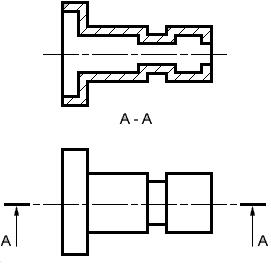
Full Sectional View

                        A Full Sectional view is used to show the object as if one half of the object was removed. The example below shows a simple single plane sectional view where object is cut in half by the cutting plane


Half Sectional View

                      A Half Section view is used to show the object as if one quarter of the object was removed.


Removed Sectional View

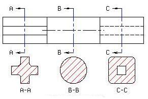
                     A Removed Sectional view is used to show the variable shape of the object from end to end.


Offset Sectional View

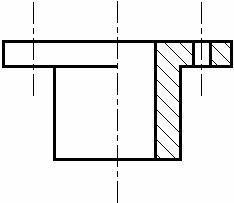
                         The section planes are usually assumed to pass through the axis of symmetry or the principal axis of the object. When several features like holes, slot, recess etc of the component do not lie on the axis of symmetry of the object the section plane may be offset, as shown in fig (6.5) to include the axes of different features.


Aligned Sectional View

                               An Aligned Sectional view is used to show the shape of features that do not align with the vertical and horizontal centerlines of the object.

Broken - out sectional view

                     A Broken-out Sectional view is used to show the material thickness of a hollow object.

Partial Sectional View

                  A Partial Sectional view is similar to a Broken-out but usually covers a larger area but less than a Half Section. It is common practice to section a part of an object when only small areas need to be sectioned to indicate the important details.

Assembly Sectional View

                An Assembly Section is used to show the arrangement and relationship of parts that makeup an object.

Pictorial Sectional View

                        A Pictorial Section is used to show the arrangement and relationship of parts that makeup an object in a three dimensional view with a quarter to a half of the object removed.

Cutting plane representation

                            Sectional views are located by creating a Cutting Plane Line in one view. The Cutting Plane Line is a thick, dark line composed of a long dash, two short dashes and a long dash. An optional Cutting Plane Line consisting of thick, dark, long dashes may also be used. Short perpendicular lines with arrowheads pointing away from the line are added to each end to indicate the viewing direction or line of sight. The arrows should also point away from the view that is sectioned. Identification "Letters" (A-A, B-B, C-C, etc.) should be placed above the arrows when more than one section view is needed on a drawing.

Hatching

                          "Section Lining" or "Cross Hatching" or "Hatching" is added to the Section view to distinguish the solid portions from the hollow areas of an object and can also be used to indicate the type of material that was used to make the object. General Purpose "Section Lining", which is also used to represent "Cast Iron", uses medium, thick, lines drawn at a 45° angle and spaced 1/8" apart. Different materials have different patterns of lines and spacing. Section lining should be reversed or mirrored on adjoining parts when doing an Assembly Section.
· To avoid confusion, "Hidden Lines" are omitted from Section views.
· Spokes (that are used to hold the rim and hub of a wheel together) and ribs (that are used to reinforce or support a hub and a plate) are not sectioned.
· Keys, key ways, nuts, bolts and other fasteners on Assembly Sections are not sectioned.
SOLAR RADIATION AT THE EARTH SURFACE

While the solar radiation incident on the Earth's atmosphere is relatively constant, the radiation at the Earth's surface varies widely due to:
  • atmospheric effects, including absorption and scattering;
  • local variations in the atmosphere, such as water vapour, clouds, and pollution;
  • latitude of the location; and
  • the season of the year and the time of day.
The above effects have several impacts on the solar radiation received at the Earth's surface. These changes include variations in the overall power received, the spectral content of the light and the angle from which light is incident on a surface. In addition, a key change is that the variability of the solar radiation at a particular location increases dramatically. The variability is due to both local effects such as clouds and seasonal variations, as well as other effects such as the length of the day at a particular latitude. Desert regions tend to have lower variations due to local atmospheric phenomena such as clouds. Equatorial regions have low variability between seasons.

CLASSIFICATIONS OF FLUIDS

The types of fluids as shown in follows
         
                            1. Ideal Fluids
                            
                            2. Real Fluids

                            3. Newtonian Fluids
 
                            4. Non - Newtonian Fluids

ELASTICITY

                               In physics, elasticity is a physical property of materials which return to their original shape after they are deformed.
                               Elasticity is the measurement of how changing one economic variable affects others.

FUELS

                Fuels are any materials that store potential energy in forms that can be practicably released and used as heat energy. The concept originally applied solely to those materials storing energy in the form of chemical energy that could be released through combustion, but the concept has since been also applied to other sources of heat energy such as nuclear energy (via nuclear fission or nuclear fusion), as well as releases of chemical energy released through non-combustion oxidation (such as in cellular biology or in fuel cells).
                
                 A substance that produces useful energy when it undergoes a chemical or nuclear reaction.
 
                  A material such as wood, coal, gas, or oil burned to produce heat or power.

PROCEDURE FOR DESIGNING MACHINE ELEMENTS

Though the machine design procedure is not standard, there are some common steps to be followed; these can be followed as per the requirements wherever and whenever necessary. Here are some guidelines as to how the machine design engineer can proceed with the design:
1) Making the written statement: Make the written statement of what exactly is the problem for which the machine design has to be done. This statement should be very clear and as detailed as possible. If you want to develop the new produce write down the details about the project. This statement is sort of the list of the aims that are to be achieved from machine design.
2) Consider the possible mechanisms: When you designing the machine consider all the possible mechanisms which help desired motion or the group of motions in your proposed machine. From the various options the best can be selected whenever required.
3) Transmitted forces: Machine is made up of various machine elements on which various forces are applied. Calculate the forces acting on each of the element and energy transmitted by them.
4) Material selection: Select the appropriate materials for each element of the machine so that they can sustain all the forces and at the same time they have least possible cost.
5) Find allowable stress: All the machine elements are subjected to stress whether small or large. Considering the various forces acting on the machine elements, their material and other factors that affect the strength of the machine calculate the allowable or design stress for the machine elements.
6) Dimensions of the machine elements: Find out the appropriate dimensions for the machine elements considering the forces acting on it, its material, and design stress. The size of the machine elements should be such that they should not distort or break when loads are applied.
7) Consider the past experience: If you have the past experience of designing the machine element or the previous records of the company, consider them and make the necessary changes in the design. Further, designer can also consider the personal judgment so as to facilitate the production of the machine and machine elements.
8) Make drawings: After designing the machine and machine elements make the assembly drawings of the whole machines and detailed drawings of all the elements of the machine. In the drawings clearly specify the dimensions of the assembly and the machine elements, their total number required, their material and method of their production. The designer should also specify the accuracy, surface finish and other related parameters for the machine elements.

HIGH CARBON STEEL

                    Steel that has more than 0.3 percent carbon, and is thus harder and less formable and machinable than low-carbon steel. Used mainly for cutting EDGEs, compression springs, farming and gardening equipment, and other high-wear applications.
                    Carbon steel is steel where the main interstitial alloying constituent is carbon in the range of 0.12-2.0%. The American Iron and Steel Institute (AISI) defines carbon steel as the following: "Steel is considered to be carbon steel when no minimum content is specified or required for chromium, cobalt, molybdenum, nickel, niobium, titanium, tungsten, vanadium or zirconium, or any other element to be added to obtain a desired alloying effect; when the specified minimum for copper does not exceed 0.40 percent; or when the maximum content specified for any of the following elements does not exceed the percentages noted: manganese 1.65, silicon 0.60, copper 0.60."

                    The term "carbon steel" may also be used in reference to steel which is not stainless steel; in this use carbon steel may include alloy steels.

                    As the carbon percentage content rises, steel has the ability to become harder and stronger through heat treating, however it becomes less ductile. Regardless of the heat treatment, a higher carbon content reduces weldability. In carbon steels, the higher carbon content lowers the melting point.

WEIGHT

                                    In science and engineering, the weight of an object is usually taken to be the force on the object due to gravity. Its magnitude (a scalar quantity), often denoted by an italic letter W, is the product of the mass m of the object and the magnitude of the local gravitational acceleration g; thus: W = mg. The term weight and mass are often confused with each other in everyday discourse but they are distinct quantities. The unit of measurement for weight is that of force, which in the International System of Units (SI) is the newton.

TYPES OF PATTERNS

Single Piece Pattern

Split Pattern


Loose Piece Pattern


FACTORS FOR SELECTING PATTERN MATERIALS

The following factors assist in selecting proper pattern material:
sunbul.png No. of castings to be produced.
sunbul.png Metal to be cast.
sunbul.png Dimensional accuracy & surface finish.
sunbul.png Shape, complexity and size of casting.
sunbul.png Casting design parameters.
sunbul.png Type of molding materials.
sunbul.png The chance of repeat orders.
sunbul.png Nature of molding process.
sunbul.png Position of core print.

Friday, 24 May 2013

TYPES OF SECTIONAL VIEWS

  1. Full Section
  2. Half Section
  3. Offset Section
  4. Revolved Section
  5. Broken Section
  6. Removed Section

SOLAR ENERGY

                        Solar energy, radiant light and heat from the sun, has been harnessed by humans since ancient times using a range of ever-evolving technologies. Solar energy technologies include solar heating, solar photovoltaics, solar thermal electricity, solar architecture and artificial photosynthesis, which can make considerable contributions to solving some of the most urgent energy problems the world now faces.

FLUID

                       In physics, a fluid is a substance that continually deforms (flows) under an applied shear stress. Fluids are a super set of the phases of matter and include liquids, gases, plasmas and, to some extent, plastic solids.

STRENGTH

               Strength is the ability of a material to resist deformation. The strength of a component is usually considered based on the maximum load that can be borne before failure is apparent.

THERMODYNAMICS

                        Thermodynamics is a branch of natural science concerned with heat and its relation to energy and work. It defines macroscopic variables (such as temperatureinternal energyentropy, and pressure) that characterize materials and radiation, and explains how they are related and by what laws they change with time. Thermodynamics describes the average behavior of very large numbers of microscopic constituents, and its laws can be derived from statistical mechanics.

PATTERNS

                 In casting, a pattern is a replica of the object to be cast, used to prepare the cavity into which molten material will be poured during the casting process. Patterns used in sand casting may be made of wood, metal, plastics or other materials. Patterns are made to exacting standards of construction, so that they can last for a reasonable length of time, according to the quality grade of the pattern being built, and so that they will repeatably provide a dimensionally acceptable casting. Under certain circumstances an original item may be adapted to be used as a pattern. The making of patterns, called pattern making (sometimes styled pattern-making or pattern making), is a skilled trade that is related to the trades of tool and die making and mold making, but also often incorporates elements of fine woodworking. Pattern makers (sometimes styled pattern-makers or pattern makers) learn their skills through apprenticeships and trade schools over many years of experience. Although an engineer may help to design the pattern, it is usually a pattern maker who executes the design.

SECTIONAL VIEWS

                   In an orthographic projection drawing, outlines and edges of an object are usually depicted with continuous lines and internal details are normally illustrated by using hidden lines. When dealing with complex objects, there may be many hidden lines and these hidden lines may become very confusing. Thus, you can use sectioning technique to ‘ cut sections’ across the object to show internal details.


ENERGY

             In physics, energy is an indirectly observed quantity which comes in many forms, such as kinetic energypotential energyradiant energy, and many others; which are listed in this summary article.

FLUID MECHANICS

                         Fluid mechanics is the branch of physics that studies fluids (liquidsgases, and plasmas) and the forces on them. Fluid mechanics can be divided into fluid statics, the study of fluids at rest; fluid kinematics, the study of fluids in motion; and fluid dynamics, the study of the effect of forces on fluid motion.

ENGINEERING MATERIALS

          There are two types of engineering materials.

                               1. Ferrous materials
                               
                               2. Non - Ferrous materials

CUTTING TOOL MATERIAL

                   Cutting tool is a device used to remove unwanted material from the given workpiece.

Characteristics of a cutting tool material

       1.   The material should be harder than the workpiece so that it is able to penetrate into the workpiece and it should have hot hardness i.e. the ability of material to retain hardness at elevated temperatures.
2.   The coefficient of friction at the tool chip interface should be low for better surface finish and less wear.
3.   The material should have wear resistance to prevent wear and tear of the cutting tool surface.
4.   It should be chemically stable so that it does not react with the workpiece and chemically inert so that there is no oxidation and hence no scales and pits are formed on the surface.
5.   The material must have sufficient strength and toughness to withstand shocks and vibrations.
6.   The thermal conductivity should be high so that there is heat dissipation which is generated during the machining process thereby increasing the life of the cutting tool.

STEAM

                           Steam is the technical term for water vapor, the gaseous phase of water, which is formed when water boils. Water vapor cannot be seen, though in common language it is often used to refer to the visible mist of water droplets formed as this water vapor condenses in the presence of cooler air.

Thursday, 23 May 2013

POWER

          In physicspower is the rate at which energy is transferred, used, or transformed. The unit of power is the joule per second (J/s), known as the watt (in honor of James Watt, the eighteenth-century developer of the steam engine). For example, the rate at which a light bulb transforms electrical energy into heat and light is measured in watts—the more wattage, the more power, or equivalently the more electrical energy is used per unit time.

                              Common Symbol of Power is P.
                              SI Unit of power is watt.

NEWTON'S FIRST LAW OF MOTION

       Newton's first law of motion is often stated as

An object at rest stays at rest and an object in motion stays in motion with the same speed and in the same direction unless acted upon by an unbalanced force.


                            There are two parts to this statement - one that predicts the behavior of stationary objects and the other that predicts the behavior of moving objects. The two parts are summarized in the following diagram.


Suppose that you filled a baking dish to the rim with water and walked around an oval track making an attempt to complete a lap in the least amount of time. The water would have a tendency to spill from the container during specific locations on the track. In general the water spilled when:
  • the container was at rest and you attempted to move it
  • the container was in motion and you attempted to stop it
  • the container was moving in one direction and you attempted to change its direction.
                  The water spills whenever the state of motion of the container is changed. The water resisted this change in its own state of motion. The water tended to "keep on doing what it was doing." The container was moved from rest to a high speed at the starting line; the water remained at rest and spilled onto the table. The container was stopped near the finish line; the water kept moving and spilled over container's leading edge. The container was forced to move in a different direction to make it around a curve; the water kept moving in the same direction and spilled over its edge. The behavior of the water during the lap around the track can be explained by Newton's first law of motion.

SECOND

                                    The second (symbol: s) is the base unit of time in the International System of Units (SI) and is also a unit of time in other systems of measurement (abbreviated s or sec) it is the second division of the hour by sixty, the first division by 60 being the minute.Between 1000  and 1960 the second was defined as 1/86,400 of a mean solar day (that definition still applies in some astronomical and legal contexts). Between 1960 and 1967, it was defined in terms of the period of the Earth's orbit around the Sun in 1900, but it is now defined more precisely in atomic terms. Seconds may be measured using mechanical, electric or atomic clocks.

KILOGRAM

                                     The kilogram or kilogramme is the base unit of mass in the International System of Units and is defined as being equal to the mass of the International Prototype of the Kilogram (IPK) The avoirdupois (or international) pound, used in both the Imperial system and U.S. customary units, is defined as exactly 0.45359237 kg, making one kilogram approximately equal to 2.2046 avoirdupois pounds.

METRE

                           The metre is the fundamental unit of length in the International System of Units (SI). Originally intended to be one ten-millionth of the distance from the Earth's equator to the North Pole (at sea level), its definition has been periodically refined to reflect growing knowledge of metrology. Since 1983, it has been defined as "the length of the path travelled by light in vacuum during a time interval of 1/299,792,458 of a second."

MASS

                           In physicsmass refers to the quantity of matter in an object. More specifically, inertial mass is a quantitative measure of an object's resistance to acceleration. In addition to this,gravitational mass is a quantitative measure that is proportional to the magnitude of the gravitational force which is

  1. exerted by an object (active gravitational mass), or
  2. experienced by an object (passive gravitational force)

when interacting with a second object. The SI unit of mass is the kilogram (kg).

OTTO CYCLE

An Otto cycle is an idealized thermodynamic cycle which describes the functioning of a typical spark ignition reciprocating piston engine,[1] the thermodynamic cycle most commonly found in automobile engines.
The Otto cycle is constructed out of:
Top and bottom of the loop: a pair of quasi-parallel adiabatic processes
Left and right sides of the loop: a pair of parallel isochoric processes

The adiabatic processes are impermeable to heat: heat flows into the loop through the left pressurizing process and some of it flows back out through the right depressurizing process, and the heat which remains does the work.
The processes are described by:
  • Process 1-2 is an isentropic compression of the air as the piston moves from bottom dead centre (BDC) to top dead centre (TDC).
  • Process 2-3 is a constant-volume heat transfer to the air from an external source while the piston is at top dead centre. This process is intended to represent the ignition of the fuel-air mixture and the subsequent rapid burning.
  • Process 3-4 is an isentropic expansion (power stroke).
  • Process 4-1 completes the cycle by a constant-volume process in which heat is rejected from the air while the piston is a bottom dead centre.
                              The Otto cycle consists of adiabatic compression, heat addition at constant volume, adiabatic expansion, and rejection of heat at constant volume. In the case of a four-stroke Otto cycle, technically there are two additional processes: one for the exhaust of waste heat and combustion products (by isobaric compression), and one for the intake of cool oxygen-rich air (by isobaric expansion); however, these are often omitted in a simplified analysis. Even though these two processes are critical to the functioning of a real engine, wherein the details of heat transfer and combustion chemistry are relevant, for the simplified analysis of the thermodynamic cycle, it is simpler and more convenient to assume that all of the waste-heat is removed during a single volume change.
                              A Pressure - Volume and Temperature - Entropy diagram of the Otto cycle is very useful in the analysis of the entire process.
                              The first person to build a working four stroke engine, a stationary engine using a coal gas-air mixture for fuel (a gas engine), was German engineer Nicolaus Otto. This is why the four-stroke principle today is commonly known as the Otto cycle and four-stroke engines using spark plugs often are called Otto engines.
                              
Pressure - Volume Diagram

Temperature - Entropy Diagram

Process 1-2

Piston moves from crank end (bottom dead centre) to cover end (top dead centre) and an ideal gas with initial state 1 is compressed isentropically to state point 2, through compression ratio ({V}_{1}/{V}_{2}). Mechanically this is the adiabatic compression of the air/fuel mixture in the cylinder, also known as the compression stroke. Generally the compression ratio is around 9-10:1 (V1:V2) for a typical engine.


Process 2-3

The piston is momentarily at rest at TDC and heat is added to the working fluid at constant volume from an external heat source which is brought into contact with the cylinder head. The pressure rises and the ratio ({P}_{3}/{P}_{2}) is called the "explosion ratio". At this instant the air/fuel mixture is compressed at the top of the compression stroke with the volume essentially held constant, also known as ignition phase.


Process 3-4

The increased high pressure exerts a greater amount of force on the piston and pushes it towards the BDC. Expansion of working fluid takes place isentropically and work is done by the system. The volume ratio ({V}_{4}/{V}_{3}) is called "isentropic expansion ratio". Mechanically this is the adiabatic expansion of the hot gaseous mixture in the cylinder head, also known as expansion (power) stroke.


Process 4-1

The piston is momentarily at rest at BDC and heat is rejected to the external sink by bringing it in contact with the cylinder head. The process is so controlled that ultimately the working fluid comes to its initial state 1 and the cycle is completed.


Exhaust and intake strokes

Exhaust stroke-ejection of the gaseous mixture via an exhaust valve through the cylinder head. Induction stroke-intake of the next air charge into the cylinder. The volume of the exhaust gasses is the same as the air charge.


Diagram for Otto cycle stages


Cycle analysis


Processes 1-2 and 3-4 do work on the system but no heat transfer occurs during adiabatic expansion and compression. Processes 2-3 and 4-1 are isochoric; therefore, heat transfer occurs but no work is done. No work is done during an isochoric (constant volume) because work requires movement; when the piston volume does not change no shaft work is produced by the system. Four different equations can be derived by neglecting kinetic and potential energy and considering the first law of thermodynamics (energy conservation). Assuming these conditions the first law is rewritten as:
\Delta{\mathit{E}}=\Delta{\mathit{U}}=\mathit{Q}_{in}-\mathit{W}_{out}
Applying this to the Otto cycle the four process equations can be derived:
\left(\frac{\mathit{W}_{1-2}}{{m}}\right)=\mathit{u}_2-\mathit{u}_1
\left(\frac{\mathit{W}_{3-4}}{{m}}\right)=\mathit{u}_3-\mathit{u}_4
\left(\frac{\mathit{Q}_{2-3}}{{m}}\right)=\mathit{u}_3-\mathit{u}_2
\left(\frac{\mathit{Q}_{4-1}}{{m}}\right)=\mathit{u}_4-\mathit{u}_1

Since the first law is expressed as heat added to the system and work expelled from the system then (\mathit{W}_{1-2}/{m}) and (\mathit{Q}_{4-1}/{m}) will always produce positive values. However, since work always involves movement, processes 2-3 and 4-1 will be omitted because they occur at a constant volume. The net work can be expressed as:

\left(\frac{\mathit{W}_{cycle}}{{m}}\right)=\left(\frac{\mathit{W}_{3-4}}{{m}}\right)-\left(\frac{\mathit{W}_{1-2}}{{m}}\right)=(\mathit{u}_3-\mathit{u}_4)-(\mathit{u}_2-\mathit{u}_1)
The net work can also be found by evaluating the heat added minus the heat leaving or expelled.
\left(\frac{\mathit{W}_{cycle}}{{m}}\right)=\left(\frac{\mathit{Q}_{2-3}}{{m}}\right)-\left(\frac{\mathit{Q}_{4-1}}{{m}}\right)=(\mathit{u}_3-\mathit{u}_2)-(\mathit{u}_4-\mathit{u}_1)
Thermal efficiency is the quotient of the net work to the heat addition into system. Upon rearrangement the thermal efficiency can be obtained (Net Work/Heat added):
Equation 1:
\eta=\left(\frac{(\mathit{u}_3-\mathit{u}_2)-(\mathit{u}_4-\mathit{u}_1)}{\mathit{u}_3-\mathit{u}_2}\right)=1-\left(\frac{\mathit{u}_{4}-\mathit{u}_{1}}{\mathit{u}_{3}-\mathit{u}_{2}}\right)
Alternatively, thermal efficiency can be derived by strictly heat added and heat rejected.
\eta=\left(\frac{{heat}_{supplied}-{heat}_{rejected}}{{heat}_{supplied}}\right)
\eta=1-\left(\frac{{heat}_{rejected}}{{heat}_{supplied}}\right)
\eta=1-\left(\frac{\mathit{Q}_{out}}{\mathit{Q}_{in}}\right)

In the Otto cycle, there is no heat transfer during the process 1-2 and 3-4 as they are reversible adiabatic processes. Heat is supplied only during the constant volume processes 2-3 and heat is rejected only during the constant volume processes 4-1.[7]
Equation 1 can now be related to the specific heat equation for constant volume. The specific heats are particularly useful for thermodynamic calculations involving the ideal gas model.
{\mathit{c}_{v}}=\left(\frac{\delta{\mathit{u}}}{\delta{T}}\right)_{v}
Rearranging yields:
\mathit{u}=({\mathit{c}_{v}})({\delta{T}})
Inserting the specific heat equation into the thermal efficiency equation (Equation 1) yields.
\eta=1-\left(\frac{\mathit{c}_{v}(\mathit{T}_{4}-\mathit{T}_{1})}{\mathit{c}_{v}(\mathit{T}_{3}-\mathit{T}_{2})}\right)
Upon rearrangement:
\eta=1-\left(\frac{\mathit{T}_{1}}{\mathit{T}_{2}}\right)\left(\frac{\mathit{T}_{4}/\mathit{T}_{1}-1}{\mathit{T}_{3}/\mathit{T}_{2}-1}\right)
Next, noting from the diagrams {T}_{4}/{T}_{1}={T}_{3}/{T}_{2}, thus both of these can be omitted. The equation then reduces to:
Equation 2:
\eta=1-\left(\frac{\mathit{T}_{1}}{\mathit{T}_{2}}\right)

Since the Otto cycle is an isentropic process the isentropic equations of ideal gases and the constant pressure/volume relations can be used to yield Equations 3 & 4.
Equation 3:
\left(\frac{{T}_{2}}{{T}_{1}}\right)=\left(\frac{{p}_{2}}{{p}_{1}}\right)^{(\gamma-1)/{\gamma}}
Equation 4:
\left(\frac{{T}_{2}}{{T}_{1}}\right)=\left(\frac{{V}_{1}}{{V}_{2}}\right)^{(\gamma-1)}imagine
The derivation of the previous equations are found by solving these four equations respectively (where R is the gas constant):
\mathit{{c}_{p}}\mathit{ln}\left(\frac{{V}_{1}}{{V}_{2}}\right)-\mathit{R}\mathit{ln}\left(\frac{{p}_{2}}{{p}_{1}}\right)=0
\mathit{{c}_{v}}\mathit{ln}\left(\frac{{T}_{2}}{{V}_{1}}\right)-\mathit{R}\mathit{ln}\left(\frac{{V}_{2}}{{V}_{1}}\right)=0
\mathit{c}_{p}=\left(\frac{\mathit{KR}}{\mathit{{K}-1}}\right)
\mathit{c}_{v}=\left(\frac{\mathit{K}}{\mathit{{K}-1}}\right)
Further simplifying Equation 4, where \mathit{r} is the compression ratio ({V}_{1}/{V}_{2}):
Equation 5:
\left(\frac{{T}_{2}}{{T}_{1}}\right)=\left(\frac{{V}_{1}}{{V}_{2}}\right)^{(\gamma-1)}={r}^{(\gamma-1)}
Also, note that
{\gamma}=\left(\frac{\mathit{c}_{p}}{{c}_{v}}\right)
where {\gamma} is the specific heat ratio
From inverting Equation 4 and inserting it into Equation 2 the final thermal efficiency can be expressed as:[7]
Equation 6:
\eta=1-\left(\frac{{1}}{{r}^{(\gamma-1)}}\right)

From analyzing equation 6 it is evident that the Otto cycle efficiency depends directly upon the compression ratio \mathit{r}. Since the \gamma for air is 1.4, an increase in\mathit{r} will produce an increase in \eta. However, the \gamma  for combustion products of the fuel/air mixture is often taken at approximately 1.3. The foregoing discussion implies that it is more efficient to have a high compression ratio. The standard ratio is approximately 10:1 for typical automobiles. Usually this does not increase much because of the possibility of autoignition, or "knock", which places an upper limit on the compression ratio.[2] During the compression process 1-2 the temperature rises, therefore an increase in the compression ratio causes an increase in temperature. Autoignition occurs when the temperature of the fuel/air mixture becomes too high before it is ignited by the flame front. The compression stroke is intended to compress the products before the flame ignites the mixture. If the compression ratio is increased, the mixture may auto-ignite before the compression stroke is complete, leading to "engine knocking". This can damage engine components and will decrease the brake horsepower of the engine.