Thursday, 1 August 2013


Torque

      It may be defined as the product of force and the perpendicular distance of its line of action from the given point or axis. A little consideration will show that the torque is equivalent to a couple acting upon a body. The Newton’s second law of motion when applied to rotating bodies states, the torque is directly proportional to the rate of change of angular momentum.         

General Procedure in Machine Design

In designing a machine component, there is no rigid rule. The  problem may be attempted in several ways. However, the general procedure to solve a design problem is as follows :
     1. Recognition of need. First of all, make a complete statement of the problem, indicating the need, aim or purpose for which the machine is to be designed.
     2. Synthesis (Mechanisms). Select the possible mechanism or group of mechanisms which will give the desired motion.
     3. Analysis of forces. Find the forces acting on each member of the machine and the energy transmitted by each member.
     4. Material selection. Select the material best suited for each member of the machine.
     5. Design of elements (Size and Stresses). Find the size of each member of the machine by considering the force acting on the member and the permissible stresses for the material used. It should be kept in mind that each member should not deflect or deform than the permissible limit.
     6. Modification. Modify the size of the member to agree with the past experience and judgment to facilitate manufacture. The modification may also be necessary by consideration of manufacturing
to reduce overall cost.
     7. Detailed drawing. Draw the detailed drawing of each component and the assembly of the
machine with complete specification for the manufacturing processes suggested.
     8. Production. The component, as per the drawing, is manufactured in the workshop.

Classifications of Machine Design

The machine design may be classified as follows :
1. Adaptive design. In most cases, the designer’s work is concerned with adaptation of existing
designs. This type of design needs no special knowledge or skill and can be attempted by designers of
ordinary technical training. The designer only makes minor alternation or modification in the existing
designs of the product.
2. Development design. This type of design needs considerable scientific training and design
ability in order to modify the existing designs into a new idea by adopting a new material or different
method of manufacture. In this case, though the designer starts from the existing design, but the final
product may differ quite markedly from the original product.
3. New design. This type of design needs lot of research, technical ability and creative thinking. Only those designers who have personal qualities of a sufficiently high order can take up the
work of a new design.
The designs, depending upon the methods used, may be classified as follows :
(a) Rational design. This type of design depends upon mathematical formulae of principle of
mechanics.
(b) Empirical design. This type of design depends upon empirical formulae based on the practice
and past experience.
(c) Industrial design. This type of design depends upon the production aspects to manufacture
any machine component in the industry.
(d) Optimum design. It is the best design for the given objective function under the specified
constraints. It may be achieved by minimising the undesirable effects.
(e) System design. It is the design of any complex mechanical system like a motor car.
(f) Element design. It is the design of any element of the mechanical system like piston,
crankshaft, connecting rod, etc.
(g) Computer aided design. This type of design depends upon the use of computer systems to
assist in the creation, modification, analysis and optimisation of a design.

Saturday, 25 May 2013


PROPERTIES OF FLUIDS

                              1. Density
                    
                              2. Specific weight (weight density)

                              3. Specific Volume
   
                              4. Relative density (Specific gravity)

                              5. Compressibility

                              6. Cohesion

                              7. Adhesion

                              8. Viscosity

                              9. Kinematic Viscosity

                             10. Surface Tension

                             11. Capillarity

                             12. Vapour Pressure

PLASTICITY

                    In Engineering plasticity is the propensity of a material to undergo permanent deformation under load.

TYPES OF SECTIONAL VIEWS

Full Sectional View

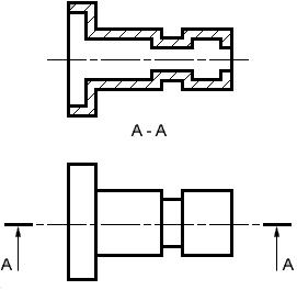
                        A Full Sectional view is used to show the object as if one half of the object was removed. The example below shows a simple single plane sectional view where object is cut in half by the cutting plane


Half Sectional View

                      A Half Section view is used to show the object as if one quarter of the object was removed.


Removed Sectional View

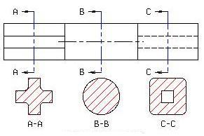
                     A Removed Sectional view is used to show the variable shape of the object from end to end.


Offset Sectional View

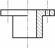
                         The section planes are usually assumed to pass through the axis of symmetry or the principal axis of the object. When several features like holes, slot, recess etc of the component do not lie on the axis of symmetry of the object the section plane may be offset, as shown in fig (6.5) to include the axes of different features.


Aligned Sectional View

                               An Aligned Sectional view is used to show the shape of features that do not align with the vertical and horizontal centerlines of the object.

Broken - out sectional view

                     A Broken-out Sectional view is used to show the material thickness of a hollow object.

Partial Sectional View

                  A Partial Sectional view is similar to a Broken-out but usually covers a larger area but less than a Half Section. It is common practice to section a part of an object when only small areas need to be sectioned to indicate the important details.

Assembly Sectional View

                An Assembly Section is used to show the arrangement and relationship of parts that makeup an object.

Pictorial Sectional View

                        A Pictorial Section is used to show the arrangement and relationship of parts that makeup an object in a three dimensional view with a quarter to a half of the object removed.

Cutting plane representation

                            Sectional views are located by creating a Cutting Plane Line in one view. The Cutting Plane Line is a thick, dark line composed of a long dash, two short dashes and a long dash. An optional Cutting Plane Line consisting of thick, dark, long dashes may also be used. Short perpendicular lines with arrowheads pointing away from the line are added to each end to indicate the viewing direction or line of sight. The arrows should also point away from the view that is sectioned. Identification "Letters" (A-A, B-B, C-C, etc.) should be placed above the arrows when more than one section view is needed on a drawing.

Hatching

                          "Section Lining" or "Cross Hatching" or "Hatching" is added to the Section view to distinguish the solid portions from the hollow areas of an object and can also be used to indicate the type of material that was used to make the object. General Purpose "Section Lining", which is also used to represent "Cast Iron", uses medium, thick, lines drawn at a 45° angle and spaced 1/8" apart. Different materials have different patterns of lines and spacing. Section lining should be reversed or mirrored on adjoining parts when doing an Assembly Section.
· To avoid confusion, "Hidden Lines" are omitted from Section views.
· Spokes (that are used to hold the rim and hub of a wheel together) and ribs (that are used to reinforce or support a hub and a plate) are not sectioned.
· Keys, key ways, nuts, bolts and other fasteners on Assembly Sections are not sectioned.
SOLAR RADIATION AT THE EARTH SURFACE

While the solar radiation incident on the Earth's atmosphere is relatively constant, the radiation at the Earth's surface varies widely due to:
  • atmospheric effects, including absorption and scattering;
  • local variations in the atmosphere, such as water vapour, clouds, and pollution;
  • latitude of the location; and
  • the season of the year and the time of day.
The above effects have several impacts on the solar radiation received at the Earth's surface. These changes include variations in the overall power received, the spectral content of the light and the angle from which light is incident on a surface. In addition, a key change is that the variability of the solar radiation at a particular location increases dramatically. The variability is due to both local effects such as clouds and seasonal variations, as well as other effects such as the length of the day at a particular latitude. Desert regions tend to have lower variations due to local atmospheric phenomena such as clouds. Equatorial regions have low variability between seasons.